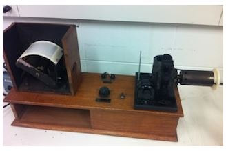
Manufacturer: General Radio Company (USA)
Model: 338, S#150
Vintage: 1928
Purpose: String Oscillograph
Condition: Restored, Working
Comments:
The 338 string oscillograph does not have a cathode ray tube as a display. Actually it has no vacuum tubes at all.
General Radio started selling these instruments in 1928. The first cathode ray tube oscillographs were commercially available in 1931.
As the name indicates this instruments uses an oscillating string as "sensor". The AC input signal is across a fine tungsten string, which will swing according to the signal. A light beam shines on the string is focused and pointed to a rotating mirror drum. The drum rotates at an adjustable speed. Above the drum is a translucent sheet for displaying the signal. The drum has an octagon, so that a stroboscope effect is created. So, if the RPM of the drum is a multiple of the input signal frequency, there is a standing wave visible.
More details are in the brochures below.
By 1930, there were a couple variations and options available, even a photo camera was available to record the wave display.
This string oscillograph was in original condition when purchased. Of course all of the electrical parts had to be replaced. Interesting enough, the light bulb was still working. The bulb is a type 1110, 6-8V, 21 & 21 CP headlight bulb, made by GE or MAZDA. Basically a typical car headlight bulb from the 20s. The mirror drum had to be newly plated. Most of the wiring had to be replaced. Fortunately the motor was still working. I decided to restore this instrument because it is so simple and so much more interesting when working.
The practical bandwidth of the instrument is about 1kHz. This is with the tungsten wire I used. It was the thinnest I could find (0.02mm). An even thinner wire may result in a higher bandwidth but then it will also be more difficult to solder to the holder and more sensitive to overvoltage. When I received the unit, there was even a small flask of oil in the drawer, for dampening resonance of the wire.
Another difficulty was focusing the wire (shadow) onto the drum. The translucent plastic screen is not perfectly equal distance from the drum at every point, so you have to pick a sweet spot.
Finally keeping the motor speed constant was difficult to produce a standing wave. The smallest change in friction changes the speed and varies the viewing of the signal.
It is not a precision measurement instrument by any stretch. It's main benefit IMO was with the use of two strings, measuring two signals and observing their phase difference. This was important when switching generators to the grid, for example. And at such low frequency, the instrument could do a fine job.
Documentation:
|
| ||||||||||||
|
| ||||||||||||
Another unit was restored by Prof. Michael Littman and his students at Princeton University:
Link to Princeton website...
https://commons.princeton.edu/josephhenry/string-oscillograph/
Link to Princeton website...
https://commons.princeton.edu/josephhenry/string-oscillograph/
